





BLOGSDETAILS
Waste Gas Adsorption System Design Explained for Plants
Author:shangcheng Time:2026-09-28 21:16:50 Click:181
A waste gas adsorption system looks deceptively simple: a vessel, a bed of adsorbent, and a fan. The engineering that makes it work sits in parameters most buyers never see—contact time, bed geometry, the migration of the adsorption zone through the media, and the discipline of knowing when the bed is spent. Getting these right means the outlet stays within permit for the designed service life. Getting them wrong means a bed that saturates in months instead of years, or one so oversized that half the carbon expires unused. This article explains the design logic so that engineers specifying or reviewing such a system can ask the right questions and verify the proposal.
The Adsorption Principle in System Terms
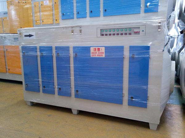
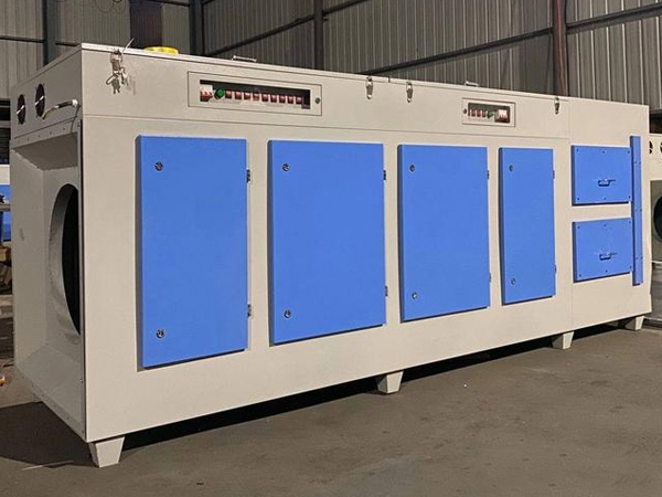
In a waste gas adsorption system, contaminated gas flows through a packed bed of granular adsorbent—usually activated carbon. VOC molecules transfer from the gas phase to the solid surface and are held there. The rate and extent of capture depend on the compound's affinity for the adsorbent, the gas velocity, the temperature, and the available surface. Design is the art of arranging these so the pollutant is captured before the gas leaves the bed, and so the bed lasts as long as the operating plan requires.
Empty-Bed Contact Time
The most cited design parameter is the empty-bed contact time (EBCT), the time the gas would spend in the bed if the voids were empty. It is calculated as bed volume divided by volumetric flow rate. For vapor-phase waste gas adsorption system design, EBCT commonly falls in the range of 0.5 to 2 seconds. Longer contact improves capture of weakly adsorbing compounds but increases vessel size and carbon volume. Shorter contact reduces cost but risks incomplete capture. The correct value is derived from the compound's adsorption isotherm and the required removal efficiency, not taken from a generic rule.
Bed Depth and Face Velocity
For a fixed EBCT, the designer can choose a shallow bed with large cross-section or a deep bed with small cross-section. Face velocity—superficial gas speed through the bed—affects both pressure drop and distribution. A waste gas adsorption system with too high a face velocity develops channeling, where gas finds low-resistance paths and bypasses carbon. Typical design face velocities keep pressure drop and channeling in check while fitting the available footprint. Bed depth also influences the length of the mass-transfer zone that the bed must accommodate.
The Mass-Transfer Zone
Adsorption does not happen uniformly across the whole bed at once. Near the inlet, the carbon saturates first; a finite region—the mass-transfer zone (MTZ)—exists where adsorption is actively occurring, bounded by fully saturated carbon behind it and fresh carbon ahead of it. As service continues, the MTZ migrates toward the outlet. The waste gas adsorption system must contain enough unused bed length ahead of the MTZ so that the zone does not reach the outlet before planned change-out. Designing the bed depth as merely the equilibrium capacity divided by load ignores the MTZ and under-specifies the system.
Breakthrough Curve
Plotting outlet concentration against time produces the breakthrough curve: a long flat low-concentration period followed by a steep rise as the MTZ exits. The design margin—how far below the permit limit the change-out is scheduled—determines safety. A robust waste gas adsorption system is swapped based on a fraction of the breakthrough capacity, not at the limit itself.
Vessel Configurations
Several configurations serve different duty profiles:
Single fixed bed: Simplest; offline change-out. Suitable when intermittent operation is acceptable.
Dual-bed (lead-lag): Two beds in series; the lead bed saturates first, then the lag bed protects the outlet. Enables near-continuous operation with staged change-out.
Moving or pulsed bed: Carbon advances through the vessel and is removed for regeneration continuously. Used in high-throughput recovery applications.
Rotary concentrator + adsorber: A zeolite wheel concentrates low-concentration VOC into a small high-concentration stream fed to a compact adsorber or oxidizer.
Sizing a Waste Gas Adsorption System
Sizing proceeds from the adsorption isotherm (equilibrium capacity at the operating concentration and temperature), the mass loading rate (flow × concentration), and the desired service interval. The adsorbent mass required equals the total VOC mass to be captured over the interval divided by the usable capacity per unit mass, with a safety factor for the MTZ and non-ideal flow. Temperature matters: higher temperature reduces capacity, so hot exhaust may need cooling before the waste gas adsorption system. Humidity also competes for sites on some adsorbents, lowering VOC capacity.
Integration and Auxiliary Design
A waste gas adsorption system rarely stands alone. Inlet pre-filtration removes particulate that would foul the bed. A demister or cooler handles moisture and temperature. Flow and pressure instrumentation confirm the system runs within design envelope. For recoverable solvents, a desorption loop with condenser and decanter returns product. Each auxiliary protects the adsorbent and extends its life; omitting pre-treatment is a frequent cause of premature saturation.
Monitoring and Control
Effective operation requires knowing the bed state. Options include:
Periodic charcoal tube or canister sampling at the outlet.
Online VOC monitoring at the outlet for critical limits.
Mass-loaded tracking: integrating flow and concentration to estimate carbon usage.
Pressure-drop trending to detect channeling or fouling.
A waste gas adsorption system without monitoring is blind; the first sign of failure is often a permit exceedance.
Common Design Mistakes
Ignoring the MTZ and sizing only on equilibrium capacity.
Using a generic EBCT without checking compound affinity.
Omitting inlet pre-filtration, leading to rapid fouling.
Failing to plan spent-carbon handling before commissioning.
Designing for average load while the peak exceeds bed capacity.
FAQ
What empty-bed contact time should a waste gas adsorption system use?
EBCT typically ranges from 0.5 to 2 seconds for vapor-phase carbon beds, but the correct value depends on the compound's adsorption isotherm and the required removal efficiency. It should be derived from testing or published isotherms, not assumed.
Why does bed depth matter more than total carbon mass alone?
The mass-transfer zone requires unused bed length ahead of it. A shallow wide bed may contain enough carbon mass but too little length to contain the MTZ, causing early breakthrough. Depth and cross-section must be designed together.
How is change-out timing determined?
By tracking mass loaded against usable capacity with a safety margin below breakthrough, confirmed by outlet monitoring. Time-based change-out without load accounting risks either premature replacement or exceedance.
Does temperature affect adsorption system design?
Yes. Higher temperature reduces adsorbent capacity, so hot exhaust may require cooling before the bed. Humidity can also compete for adsorption sites on some media, lowering VOC capture.
Conclusion
A waste gas adsorption system is defined by parameters the buyer can verify: empty-bed contact time matched to compound affinity, bed depth sufficient to contain the mass-transfer zone, vessel configuration suited to the duty, and monitoring that detects breakthrough before the permit is threatened. The practical value lies in predictable service life and reliable outlet concentration. Engineers who review proposals against these fundamentals—rather than accepting a vessel volume—will specify systems that perform as guaranteed and avoid the hidden cost of early saturation or excessive oversizing.
References
Ruthven, D. M. (1984). Principles of Adsorption and Adsorption Processes. John Wiley & Sons, New York.
Yang, R. T. (2003). Adsorbents: Fundamentals and Applications. John Wiley & Sons.
Sorial, G. A., et al. (1989). Evaluation of solid adsorbents for the removal of volatile organic compounds. Environmental Progress, 8(1), 39–52.
Khan, F. I., & Ghoshal, A. K. (2000). Removal of volatile organic compounds from polluted air. Journal of Loss Prevention in the Process Industries, 13(6), 527–545.
 HOT PRODUCT
 CONTACT US