





BLOGSDETAILS
Screw Conveyor Capacity Calculation: Complete Engineering Guide
Author:shangcheng Time:2026-10-19 16:13:28 Click:144
Accurate screw conveyor capacity calculation is essential for specifying equipment that meets your material handling requirements. This comprehensive guide provides step-by-step formulas, practical examples, and engineering data to help buyers and engineers size conveyors correctly for optimal performance.
Fundamentals of Screw Conveyor Capacity Calculation
The basic screw conveyor capacity calculation determines the volume of material a conveyor can move per unit time. This capacity depends on several interconnected factors including screw geometry, rotational speed, material properties, and conveyor inclination.
Key Variables in Capacity Calculation:
Screw Diameter (D): Inside diameter of the screw flight, typically 100-600mm
Pitch (P): Distance between successive flights, usually equal to screw diameter
Shaft Diameter (d): Central shaft size affecting available volume
RPM (N): Rotational speed of the screw
Fill Factor (f): Percentage of trough filled with material (typically 15-45%)
Material Density (ρ): Weight per unit volume of the bulk material
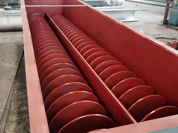
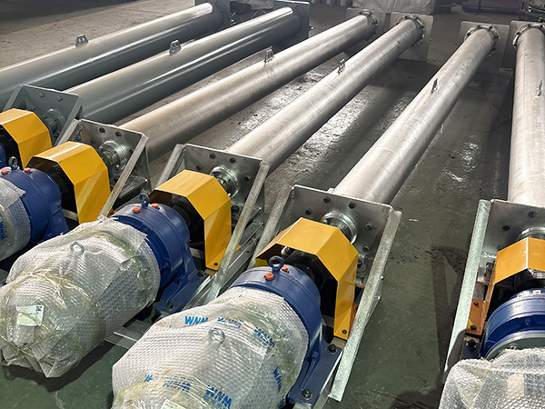
Core Capacity Formulas
1. Volumetric Capacity (Qv) - Basic Formula:
Qv = (π × D² × P × N × f) / 4
Where:
Qv = Capacity in m³/h (if D in meters)
D = Screw diameter (m)
P = Pitch (m)
N = RPM
f = Fill factor (decimal)
2. For Standard Pitch Screws (P = D):
Qv = (π × D² × N × f) / 4
3. Weight Capacity (Qw):
Qw = Qv × ρ
Where:
Qw = Weight capacity (tonnes/h)
ρ = Material bulk density (tonnes/m³)
4. Converting to Imperial Units:
Q (ft³/h) = (47.1 × D² × P × N × f)
Where D and P in inches, Q in ft³/h
Fill Factor Selection Guide
The fill factor represents the percentage of the conveyor trough occupied by material. Correct screw conveyor capacity calculation requires accurate fill factor determination based on material characteristics:
| Material Flowability | Fill Factor (%) | Typical Materials | Recommended RPM |
|---|---|---|---|
| Excellent (free-flowing) | 40-45% | Dry cement, sand, grain | 60-90 RPM |
| Good | 30-40% | Flour, sugar, powdered chemicals | 50-70 RPM |
| Fair | 20-30% | Wood chips, sawdust, coal | 30-50 RPM |
| Poor (semi-fluid) | 15-20% | Wet biomass, sludge, filter cake | 15-30 RPM |
Fill Factor Adjustments:
Incline > 10°: Reduce fill factor by 10-20%
Abrasive materials: Reduce fill factor by 10-15%
Sticky materials: Reduce fill factor by 15-25%
Temperature > 100°C: Reduce fill factor by 10%
Step-by-Step Calculation Example
Problem: Calculate the capacity of a screw conveyor with the following specifications:
Screw Diameter: 300mm (0.3m)
Pitch: 300mm (standard pitch)
RPM: 45
Material: Dry sand (bulk density 1600 kg/m³)
Fill Factor: 0.40 (40%)
Solution:
Step 1: Calculate volumetric capacity
Qv = (π × D² × N × f) / 4
Qv = (3.1416 × 0.3² × 45 × 0.40) / 4
Qv = (3.1416 × 0.09 × 45 × 0.40) / 4
Qv = (5.087) / 4
Qv = 1.27 m³/h
Step 2: Calculate weight capacity
Qw = Qv × ρ
Qw = 1.27 × 1.6 tonnes/m³
Qw = 2.03 tonnes/h
Step 3: Verify speed is within recommended range
Sand is free-flowing: 50-70 RPM recommended. 45 RPM is acceptable but could increase to 60 RPM for higher capacity.
Speed Calculation and Optimization
Screw conveyor capacity calculation requires balancing speed against material degradation and power consumption:
Maximum Recommended Speeds:
| Screw Diameter (mm) | Max RPM (Free-flowing) | Max RPM (Abrasive) | Max RPM (Sluggish) |
|---|---|---|---|
| 100-150 | 120 | 90 | 30 |
| 200-250 | 90 | 70 | 20 |
| 300-350 | 70 | 50 | 15 |
| 400-500 | 60 | 40 | 12 |
| 600+ | 45 | 30 | 10 |
Speed Reduction Factors:
Inclines > 20°: Reduce speed by 25%
Highly abrasive materials: Reduce speed by 40%
Fragile/sodegradable materials: Reduce speed by 30-50%
Sticky materials: Reduce speed by 50%
Horsepower and Torque Calculation
1. Conveyor Horsepower (HP):
HP = (Q × L × F) / 33,000
Where:
Q = Capacity (lbs/h)
L = Conveyor length (ft)
F = Material factor (1.0-1.5 typical)
2. Inclined Conveyor HP:
HP = (HPf + HPm + HPv) / η
Where:
HPf = Friction horsepower
HPm = Material horsepower
HPv = Vertical lift horsepower
η = Overall efficiency (0.85-0.95)
3. Torque Calculation:
T = (HP × 63,025) / N
Where T = torque (in-lbs), N = RPM
Material Properties Affecting Capacity
For accurate screw conveyor capacity calculation, consider:
1. Bulk Density (ρ):
Determines weight capacity vs. volumetric capacity
Varies with moisture content and compaction
Typical range: 500-2500 kg/m³
2. Angle of Repose:
Natural angle materials form when piled
Affects maximum conveyor incline
Free-flowing: 25-35°, Sluggish: 35-45°
3. Flowability Factor (Ff):
Characterizes how easily material flows
Ranges from 1.0 (excellent) to 0.5 (very poor)
Used in CEMA method calculations
4. Abrasiveness:
Mild (flour, sugar): Standard construction
Moderate (sand, mineral): Hardox liners
Severe (glass, ore): Ceramic or chromium carbide
5. Corrosiveness:
pH < 5 or > 9: Stainless steel or special alloys
Chloride content: 316 stainless minimum
Food/pharmaceutical: FDA-compliant materials
Inclined and Vertical Conveyor Adjustments
Screw conveyor capacity calculation for inclined applications requires additional corrections:
Incline Factor Chart:
| Incline Angle | Capacity Reduction | Typical Fill Factor |
|---|---|---|
| 0-5° | 0% | Standard |
| 5-10° | 10% | f × 0.90 |
| 10-15° | 20% | f × 0.80 |
| 15-20° | 30% | f × 0.70 |
| 20-25° | 40% | f × 0.60 |
| 25-30° | 55% | f × 0.45 |
Important: For inclines > 25°, consider using shaftless screws or specialty designs. Vertical screw conveyors typically require tubular housings and operate at reduced capacities (40-60% of horizontal).
Frequently Asked Questions
What is the difference between volumetric and weight capacity in screw conveyors?
Screw conveyor capacity calculation yields volumetric capacity (m³/h or ft³/h) or weight capacity (tonnes/h or lbs/h). Volumetric capacity depends only on screw dimensions and speed, while weight capacity multiplies volumetric by material bulk density. Always specify which capacity type you need when ordering equipment.
How does screw pitch affect conveyor capacity?
Pitch directly affects capacity: full-pitch screws (pitch = diameter) achieve 90% theoretical capacity. Half-pitch screws (pitch = 0.5 × diameter) provide gentler handling at 50% capacity with better mixing. Variable pitch screws meter material flow precisely. For standard applications, full-pitch is most common and efficient.
Can I increase capacity by increasing screw speed?
Capacity increases proportionally with speed, but practical limits exist. Beyond maximum recommended RPM (based on diameter and material), problems occur: material degradation, excessive wear, high power consumption, and flooding at the discharge. For significant capacity increases, consider larger diameter screws or multiple conveyors.
What is the effect of shaft diameter on screw conveyor capacity?
Central shaft reduces available volume for material. In screw conveyor capacity calculation, shaft diameter typically ranges 0.3-0.4 × screw diameter. Larger shafts provide strength for long spans but reduce capacity. Hollow pipe shafts (lightweight, better for high temperature) offer different capacity trade-offs than solid shafts.
How do I account for material moisture content in capacity calculations?
Moisture affects bulk density and flowability. Wet materials typically have 10-30% higher bulk density but reduced flowability (lower fill factor). Include moisture content in your screw conveyor capacity calculation by adjusting both density and fill factor. Request material testing from your supplier for accurate data.
Conclusion
Accurate screw conveyor capacity calculation ensures proper equipment sizing, avoiding both undersizing (causing bottlenecks) and oversizing (wasting capital). The methodology presented here follows CEMA standards and industry best practices for reliable results.
When performing screw conveyor capacity calculation, always verify material properties through testing or supplier data sheets. Apply appropriate correction factors for incline, abrasiveness, and flowability. Include safety margins of 10-15% for unexpected variations in material characteristics or operating conditions.
Partner with experienced manufacturers who provide detailed calculations, CFD analysis for complex applications, and performance guarantees. Quality suppliers offer application engineering support, helping optimize conveyor selection based on your specific material characteristics and process requirements.
References
Conveyor Equipment Manufacturers Association. (2022). CEMA Standard 350: Screw Conveyors. CEMA Press.
Perry, R.H., & Green, D.W. (2022). Perry's Chemical Engineers' Handbook (9th Edition). McGraw-Hill Education.
ISO. (2021). ISO 7194: Continuous Mechanical Handling - Belt Conveyors. International Organization for Standardization.
Fleet, I., & Kittrell, J. (2020). "Material Factors in Screw Conveyor Design." Bulk Solids Handling, 40(3), 28-35.
Roberts, A.W., & Wiche, S.J. (2021). "Optimizing Screw Conveyor Performance Through Improved Design." Powder Technology, 384, 215-229.
 HOT PRODUCT
 CONTACT US