





BLOGSDETAILS
Right Angle Pulse Valve Installation Guide for Baghouses
Author:shangcheng Time:2026-08-27 10:29:29 Click:177
The right angle pulse valve is the most common valve configuration in pulse-jet baghouses, and its installation is deceptively simple—mount it, connect the air, wire it up, and it works. The problem is that "works" and "works correctly" are not the same thing. An improperly installed valve wastes compressed air, cleans unevenly, and fails prematurely. The difference comes down to details that a careful installer catches before start-up and that a rushed one discovers after months of poor performance. This guide covers the installation steps that matter most, based on what our field technicians see go wrong most often.
Pre-Installation Inspection and Part Verification
Before touching any tools, verify the valve part number against the bill of materials. Check that the body material, diaphragm rating, and port configuration match the specification for your compressed-air pressure and process conditions. Inspect the diaphragm for shipping damage and confirm the pilot port is free of debris. A damaged diaphragm that is installed will fail within hours, and finding it after the valve is piped and wired takes three times as long. Lay out all components—valves, gaskets, fittings, and mounting hardware—and confirm everything is present before the shutdown window opens.
Mounting the Right Angle Pulse Valve Correctly
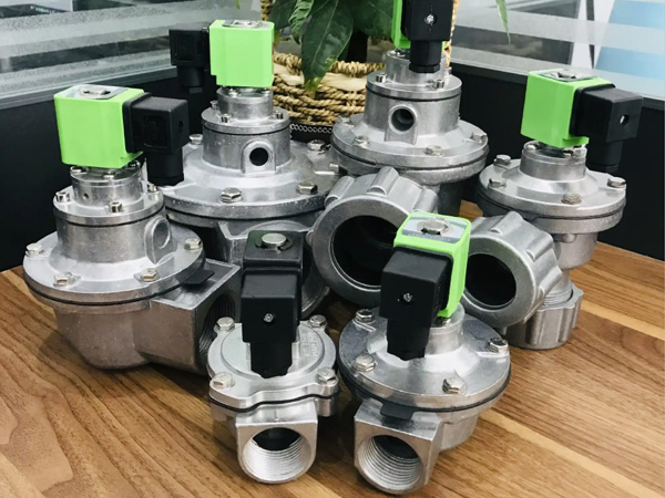
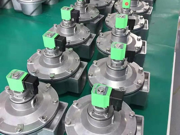
The right angle pulse valve mounts to the manifold or directly to the tube sheet adapter with the outlet pointing toward the blowpipe. The valve body must be oriented so the outlet is vertical or horizontal as specified by the manufacturer—some diaphragms are gravity-assisted and perform differently if mounted upside down. Use a new gasket at every mounting point; reused gaskets compress unevenly and leak. Torque the mounting bolts to the manufacturer's specified value, usually between 8 and 12 Nm for DN valves, using a torque wrench rather than a feel for tightness. Unevenly tightened valves leak at the body face and lose pulse energy.
Piping the Compressed Air Supply Lines
The air line between the tank and the right angle pulse valve should be as short and straight as possible to minimize pressure loss. Use appropriately sized tubing—undersized piping creates a pressure drop that reduces cleaning force at the last valve in the line. Support the piping with brackets so that vibration does not fatigue the valve body over time. Install a isolation ball valve upstream of each valve for maintenance without depressurizing the whole manifold. A point-of-use filter, ideally with a 5-micron element, protects the valve diaphragm from line debris and is inexpensive insurance against a diaphragm failure that would not have happened otherwise.
Wiring and Electrical Connection
Connect the solenoid leads using weatherproof connectors or terminal strips in a junction box that is rated for the ambient environment. The right angle pulse valve solenoid requires the correct voltage—verify 24 VDC, 110 VAC, or 220 VAC as specified before applying power. Check the polarity on DC coils; reversed polarity can cause the plunger to sit incorrectly and reduce the opening stroke. Run signal cables separately from power cables to prevent electrical interference. After wiring, test-fire each valve individually from the controller before commissioning the full row to confirm that sequencing is correct and that no wiring errors have swapped the firing order.
Commissioning: First Fire and Pressure Checks
With all valves wired and piped, pressurize the manifold slowly and check every joint for leaks using a soap solution or an ultrasonic leak detector. Listen for air escaping at the body face, the pilot port, and the blowpipe connection. Once the system is leak-free, fire each valve individually and listen for a clear pop—the sound of a properly opening diaphragm. A muffled or delayed sound indicates a restricted pilot or a damaged cartridge. Measure the pressure at the valve inlet with the tank isolated; it should match the tank pressure within 0.2 bar. If it is lower, trace the restriction upstream before proceeding.
Controller Setup and Firing Sequence Verification
Program the controller with the correct firing sequence so that adjacent rows do not pulse simultaneously. The right angle pulse valve supplier's datasheet specifies the minimum interval between pulses; if the controller allows it, add a small buffer above the minimum to protect against voltage sag under load. Set the pulse width to the recommended range—typically 80 to 120 milliseconds—and begin with the wider end of the range. You can trim it down later once the collector has stabilized and the pressure drop trend is known. Set the differential pressure alarm and trip levels before start-up so that any abnormal rise triggers an alert rather than going unnoticed.
Common Installation Errors to Avoid
The five most frequent mistakes our service team encounters are: reusing old gaskets at the valve face, mounting the valve with the outlet pointing downward instead of toward the blowpipe, undersizing the supply piping, wiring solenoid coils with reversed polarity, and failing to set the controller to stagger firing across adjacent rows. Each of these is easy to avoid with a pre-start checklist, and each causes measurable performance loss or premature failure when overlooked. Build the checklist into the commissioning procedure and have a second technician sign off before the collector goes live.
Frequently Asked Questions
Can a right angle pulse valve be mounted in any orientation?
Most valves are designed for horizontal or vertical outlet mounting. Always check the manufacturer's orientation requirements, as gravity affects diaphragm seating and opening speed.
What size piping should I use from the tank to the valve?
Size the piping to keep velocity below 6 m/s at operating pressure. Undersized piping causes pressure sag during sequential firing and weakens the pulse at the last valve in the row.
How do I test the solenoid without firing the full system?
Disconnect the lead from the controller, apply the rated voltage directly with a test lead, and listen for the solenoid click. Measure the coil resistance with a multimeter to confirm it falls within the datasheet range.
Why does my valve fire but produce no audible pop?
This usually means the pilot port is restricted or the diaphragm is not seating correctly. Check for debris in the pilot line and inspect the diaphragm for damage or incorrect orientation.
Conclusion
A properly installed right angle pulse valve delivers the cleaning performance the designer intended and runs reliably for years. The keys are careful pre-inspection, correct mounting orientation, right-sized piping, proper wiring, and disciplined commissioning. Use a checklist, test every valve before start-up, and verify the controller sequence. The time spent commissioning correctly is a fraction of the cost of chasing cleaning problems later.
References
Simon, X., et al. (2008). Pulse-jet cleaning of filter bags: effect of operating parameters. Powder Technology, 186(3), 256–264.
Fan, Y., et al. (2015). Effect of pulse parameters on cleaning performance of filter bags. Powder Technology, 271, 92–99.
Kavouras, A., et al. (2006). On the optimization of pulse-jet fabric filter cleaning. Journal of Hazardous Materials, 137(1), 59–66.
Zheng, Y., et al. (2018). Influence of solenoid valve timing on filter cleaning. Aerosol and Air Quality Research, 18(4), 1021–1030.
 HOT PRODUCT
 CONTACT US