





BLOGSDETAILS
Industrial Screw Conveyor System: Complete Working Principle and Applications Guide
Author:shangcheng Time:2026-10-18 14:39:26 Click:144
An industrial screw conveyor system represents one of the most reliable and cost-effective methods for moving bulk materials horizontally, inclined, or vertically. This comprehensive guide explains the industrial screw conveyor system working principle, component design, and selection criteria for manufacturing and processing applications.
Understanding Industrial Screw Conveyor System Working Principle
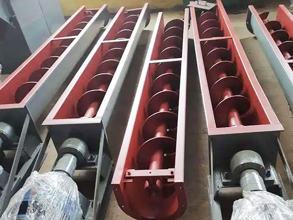
The fundamental industrial screw conveyor system working principle relies on a rotating helical screw blade (also called an auger) that pushes material forward through a tubular or U-shaped trough. As the screw rotates, material at the inlet is scooped up by the helical flights and transported along the conveyor length to the discharge point.
This mechanical conveying method operates on several key principles:
Friction Drive: Material moves due to friction between the screw flights and the bulk solid
Gravity Assist: On inclined applications, gravity helps pull material downward
Pump Action: The rotating screw creates a positive displacement effect, metering flow
Internal Pressure: Sealed housings can develop slight pressure to assist flow
The industrial screw conveyor system achieves throughput rates from 0.1 to over 1000 cubic meters per hour, depending on screw diameter, pitch, rotation speed, and material characteristics. Standard diameters range from 100mm to 600mm, with custom sizes available for specialized applications.
Core Components of Industrial Screw Conveyor System
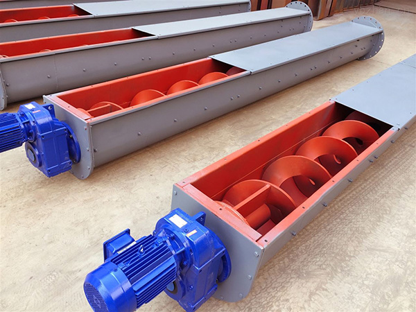
A complete industrial screw conveyor system consists of essential components that work together:
1. Screw (Auger) Assembly:
Shaft: Central steel tube or solid shaft (50-200mm diameter)
Helical Flights: Spiral steel flights welded or screwed to shaft
Flight Thickness: 4-12mm depending on material abrasion
Pitch Options: Standard (1:1), variable, or tapered
2. Trough or Housing:
U-Shaped Trough: Most common for open conveyors
Tubular Housing: Enclosed design for dust-free operation
Liner Options: Hardox, ceramic, or polyurethane for abrasive materials
3. Drive System:
Motor: 0.75-55 kW typical, gear motor or motor with belt drive
Gearbox: Helical or worm gear reducers (95-90% efficiency)
Coupling: Flexible or rigid shaft coupling
4. Support Structure:
Hangars: Bearings supporting intermediate shaft sections
Trunion Supports: For incline and vertical applications
Cradle Supports: For long horizontal runs
5. End Bearings and Seals:
Drive End Bearing: Takes radial and thrust loads
Tail End Bearing: Supports shaft, allows thermal expansion
Shaft Seals: Felt, labyrinth, or mechanical seals
Screw Conveyor Types and Configurations
Selecting the appropriate industrial screw conveyor system configuration depends on your material handling requirements:
| Conveyor Type | Application | Max Incline | Material Suitability |
|---|---|---|---|
| Horizontal Standard | Long-distance transport | 0-5° | Free-flowing to sticky materials |
| Incline Screw Conveyor | Elevating materials | 15-45° | Free-flowing materials |
| Vertical Screw Conveyor | High-lift applications | 90° | Limited to free-flowing materials |
| Live Bottom Screws | Uniform discharge | 0-20° | Variable feed rate control |
| Double Screw Conveyors | Mixing applications | 0-15° | Blending, cooling, heating |
Material Considerations and Selection
The industrial screw conveyor system working principle must adapt to various material characteristics:
Free-Flowing Materials (Grain, Sand, Cement):
Standard flight pitch and speed acceptable
Fill coefficient: 30-45% of trough capacity
Speed: 40-60 RPM typical
Semi-Flowing Materials (Sawdust, Wood Chips):
Consider variable pitch or reduced speed
Fill coefficient: 15-30% of trough capacity
Speed: 20-40 RPM typical
Abrasive Materials (Glass, Minerals, Foundry Sand):
Heavy-duty flights (6-12mm thickness)
Hardox or ceramic liner options
Reduced speed (10-30 RPM)
Sticky Materials (Clay, Wet Biomass, Sludge):
Special flight designs (ribbed, cut flights)
External bearing hangers preferred
Consider shaftless screw design
Design Parameters and Engineering Data
Key Engineering Parameters:
Screw Diameter: 100-600mm standard (larger custom available)
Conveyor Length: Up to 50 meters single section
Capacity Range: 0.1-1500 m³/h
Horsepower: 0.5-75 HP depending on application
Temperature Range: -30°C to 500°C (with special materials)
Pressure/Vacuum: Up to 2 bar sealed operation
Material Codes and Standards:
ASME B20.1: Safety Standard for Conveyors
CEMA (Conveyor Equipment Manufacturers Association) guidelines
ISO 5048: Continuous mechanical handling equipment
EU Machinery Directive 2006/42/EC compliance
Industry Applications and Case Studies
The versatile industrial screw conveyor system serves numerous industries:
Cement and Concrete Production:
Raw meal transport to kiln
Coal and pet coke handling
Fly ash and slag conveying
Capacity: 50-200 t/h typical
Food Processing:
Grain handling and storage facilities
Flour and sugar transport
Snack food processing lines
FDA-compliant stainless steel construction
Chemical Processing:
Plastic resin conveying
Dry chemical feed systems
Resin and polymer transport
ATEX-rated equipment for hazardous areas
Biomass and Renewable Energy:
Wood chip transport to boilers
Pellet conveying systems
Agricultural residue handling
Biogas plant feedstock handling
Installation and Maintenance Best Practices
Proper installation ensures optimal industrial screw conveyor system performance:
Installation Requirements:
Verify structural support alignment (max 3mm deviation per 10 meters)
Check shaft alignment (parallel within 0.5mm)
Ensure proper grounding for static discharge
Install guards per OSHA 1910.219 requirements
Test rotation direction before loading material
Preventive Maintenance Schedule:
Weekly: Visual inspection, check for unusual vibration
Monthly: Bearing temperature check, lubricant inspection
Quarterly: Flight wear measurement, seal inspection
Annually: Complete overhaul, flight replacement if worn
Frequently Asked Questions
What is the maximum incline angle for a screw conveyor?
Standard industrial screw conveyor system designs handle inclines up to 20-25° with standard pitches. For steeper angles (25-45°), use close-pitch flights or variable-pitch designs. Above 45°, consider vertical screw conveyors or bucket elevators. Material flowability significantly affects maximum incline.
How do I calculate the required horsepower for my screw conveyor?
Horsepower calculation considers material weight, conveyor length, incline angle, and friction factors. Basic formula: HP = (W × L × F) / 33,000, where W = material weight (lbs/ft), L = length (ft), F = friction factor (typically 1.0-1.5). Consult CEMA standards or manufacturer software for precise calculations including drive efficiency.
What materials are used to construct industrial screw conveyors?
Industrial screw conveyor system construction includes: carbon steel (standard applications), 304/316 stainless steel (food, pharmaceutical, corrosive materials), hardox/wear-resistant steel (abrasive materials), and special alloys (high-temperature or chemical applications). Liners of ceramic, polyurethane, or chromium carbide protect high-wear areas.
How can I prevent material degradation in screw conveyors?
Minimize degradation through: reducing screw speed (especially for fragile materials), using smooth inner trough surfaces, minimizing drop height at discharge, considering shaftless designs for sticky materials, and selecting appropriate flight clearances. Consultation with material handling engineers ensures optimal configuration.
What safety features should an industrial screw conveyor system include?
Essential safety features: shaft guards per OSHA standards, emergency stop switches, belt/pulley guards, torque-limiting devices, bearing temperature sensors, and explosion protection (relief vents, spark detection) for combustible materials. ATEX or NEC certification required for hazardous locations.
Conclusion
The industrial screw conveyor system provides proven, reliable bulk material transport for diverse industrial applications. Understanding the industrial screw conveyor system working principle enables proper selection, installation, and operation of these versatile machines.
When specifying an industrial screw conveyor system, consider material characteristics, throughput requirements, and environmental conditions. Partner with experienced manufacturers who provide engineering support, custom designs, and comprehensive documentation including ATEX certification, CE marking, and full test reports.
Quality construction using appropriate materials (stainless steel for food/pharmaceutical, hardox for abrasives) ensures long-term reliability. Implement preventive maintenance programs to maximize equipment life and minimize unplanned downtime. The industrial screw conveyor system remains a cost-effective solution for bulk material handling across cement, mining, food, chemical, and biomass industries.
References
Conveyor Equipment Manufacturers Association. (2022). CEMA Book No. 350: Screw Conveyors (5th Edition). CEMA Press.
ISO. (2021). ISO 5048:2021: Continuous Mechanical Handling Equipment - Belt Conveyors. International Organization for Standardization.
American Society of Mechanical Engineers. (2020). ASME B20.1-2020: Safety Standard for Conveyors and Related Equipment. ASME.
Koch, M., & Mutth, W. (2019). "Optimizing Screw Conveyor Performance Through Advanced Flight Design." Powder Technology, 356, 123-138.
Roberts, A.W. (2021). "Bulk Solids Handling: Engineering Principles for Conveyor Systems." Bulk Solids Handling, 41(2), 45-62.
 HOT PRODUCT
 CONTACT US