





BLOGSDETAILS
Industrial Rotary Airlock Valve: Complete Working Principle and Selection Guide
Author:shangcheng Time:2026-10-17 10:48:15 Click:104
Understanding Industrial Rotary Airlock Valve Working Principle
The fundamental industrial rotary airlock valve working principle involves a rotating rotor with multiple pockets (typically 6, 8, or 10) that continuously receives material at the inlet, carries it around the housing, and deposits it at the discharge. This design enables:
Continuous Flow: Material passes through without interrupting system pressure
Pressure Isolation: Separates vessels operating at different pressures (up to 15 bar differential)
Air Lock Function: Minimizes air/gas leakage between inlet and outlet
Volumetric Metering: Provides relatively consistent discharge rate proportional to RPM
The industrial rotary airlock valve operates by trapping material in individual rotor pockets as they pass the inlet port. The material is then carried around the housing body, typically at 10-45 RPM, before being discharged through the outlet port. Spring-loaded or pressure-loaded tip seals maintain contact between rotor blades and housing, preventing air leakage.
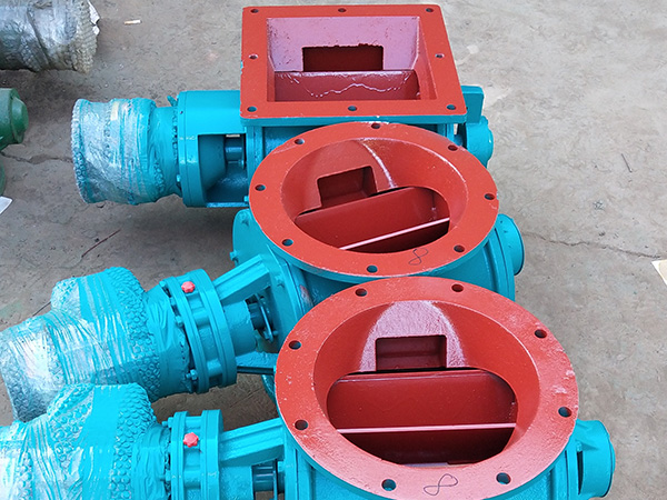
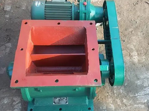
Core Components and Construction
1. Housing (Body):
Material: Cast iron, ductile iron, stainless steel (304/316), or aluminum
Ports: Inlet (top/side) and outlet (bottom/side), flanged or threaded connections
Pressure Rating: Standard 2-6 bar, high-pressure models to 15 bar
Wear Liners: Replaceable wear plates for abrasive applications
2. Rotor Assembly:
Type: Open-end, closed-end, or pocket design
Blades: 6, 8, 10, or 12 wings (more blades = better sealing, lower capacity)
Material: Steel, stainless steel, or with hard-facing coatings
Clearance: Tip clearance typically 0.2-0.5mm (adjustable for wear compensation)
3. Shaft and Bearings:
Shaft: Hardened steel, typically 40-80mm diameter
Bearings: Heavy-duty pillow block or flange bearings
Seals: V-ring, labyrinth, or mechanical shaft seals
4. Drive System:
Motor: 0.25-7.5 kW, typically direct-coupled gear motor
Speed Control: Variable frequency drive (VFD) for flow adjustment
Torque Limiter: Protects against overload (optional)
5. Sealing System:
End Plates: Bronze, carbon, or ceramic wear surfaces
Tip Seals: Spring-loaded (for dust) or pressure-loaded (for pressure service)
Purge Ports: Optional compressed air purging for improved sealing
Types of Industrial Rotary Airlock Valves
Selecting the correct industrial rotary airlock valve type depends on your application requirements:
1. Standard Duty (Star Feeders):
Application: General material handling, dust collection
Pressure: Up to 2 bar differential
RPM: 15-45 RPM typical
Material: Cast iron or aluminum
2. Heavy Duty / Pressure Feeder:
Application: Pneumatic conveying, high-pressure systems
Pressure: Up to 6-8 bar differential
RPM: 10-30 RPM
Material: Ductile iron or stainless steel
3. High-Pressure / Blow-Through:
Application: Dense phase pneumatic conveying
Pressure: Up to 10-15 bar differential
RPM: 5-20 RPM
Material: Stainless steel with hardened components
4. Drop-Through / Dumping:
Application: Gravity-fed discharge, silos
Design: Open rotor ends for complete material dumping
RPM: 5-15 RPM (controlled discharge)
Material: Various based on service
5. Thermally Protected:
Application: High-temperature materials (up to 500°C)
Features: Heat-resistant bearings, special seals, thermal expansion accommodation
Material: Heat-resistant alloys, ceramic coatings
6. Sanitary / Food Grade:
Application: Food, pharmaceutical, dairy
Features: FDA-compliant materials, CIP capability, polished surfaces
Material: 316 stainless steel, USDA-approved seals
Size Selection and Sizing Charts
Proper industrial rotary airlock valve sizing ensures optimal performance without material degradation or air leakage:
| Valve Size (inches) | Rotor Diameter (mm) | Rotor Volume (L/rev) | Capacity (m³/h at 90% fill) | Typical Motor (kW) | Max Pressure (bar) |
|---|---|---|---|---|---|
| 4 | 150 | 0.8 | 3-5 | 0.37 | 2 |
| 6 | 200 | 2.5 | 8-15 | 0.55 | 2 |
| 8 | 250 | 5.0 | 18-30 | 0.75 | 2 |
| 10 | 300 | 10.0 | 35-55 | 1.1 | 2 |
| 12 | 350 | 16.0 | 55-90 | 1.5 | 2 |
| 14 | 400 | 25.0 | 90-140 | 2.2 | 1.5 |
| 16 | 450 | 38.0 | 130-200 | 3.0 | 1 |
Important: Capacity values assume 90% fill efficiency. Actual capacity is typically 60-80% due to incomplete pocket filling. Consider safety factors of 1.2-1.5 when specifying valve size for your application.
Industrial Applications
The versatile industrial rotary airlock valve serves numerous applications:
1. Dust Collection Systems:
Hopper discharge under baghouse filters
Bin vent filter discharge
cyclone separator discharge
Capacity: 0.5-50 m³/h typical
2. Pneumatic Conveying:
Pressure conveying feeders (up to 6 bar)
Vacuum conveying receivers
Dense phase and lean phase systems
Capacity: 0.5-200+ m³/h
3. Silo and Bin Discharge:
Gravity flow metering from storage vessels
Feeding weigh hoppers and process equipment
Controlling discharge rate
4. Processing Industries:
Cement and concrete production
Chemical and plastic processing
Food, feed, and grain handling
Pharmaceutical manufacturing
Selection Criteria and Engineering Considerations
Key Selection Parameters:
1. Pressure/Temperature Requirements:
Maximum differential pressure (0-15 bar)
Operating temperature (-30°C to 500°C)
ATEX Zone classification (if applicable)
2. Material Characteristics:
Bulk density: Affects capacity and power requirements
Abrasiveness: Determines wear liner requirements
Flowability: Influences fill efficiency
Temperature: May require special materials
Chemical compatibility: With valve construction materials
3. Performance Requirements:
Air leakage tolerance: Tight sealing vs. some leakage acceptable
Capacity range: Fixed or variable throughput needed
Fill efficiency: Affects system balance
4. Environmental and Safety:
ATEX/IECEx certification for hazardous locations
FDA/USDA compliance for food applications
Noise level requirements
Maintenance accessibility
Installation and Operating Guidelines
Proper installation ensures reliable industrial rotary airlock valve performance:
Installation Requirements:
Alignment: Verify shaft alignment within 0.1mm tolerance
Support: Provide adequate structural support for weight and vibration
Drive Orientation: Ensure proper rotation direction (verify arrow marking)
Electrical: Connect motor per nameplate voltage and local codes
Purging: If equipped, connect purge air supply (30-50 mbar above system pressure)
Startup Procedure:
Verify all fasteners are tight
Lubricate bearings per manufacturer recommendations
Manually rotate rotor to check for binding
Start motor and verify rotation direction
Check for unusual noise or vibration
Verify discharge before introducing material
Maintenance Schedule:
Daily: Visual inspection, listen for unusual noise
Weekly: Check bearing temperatures, vibration levels
Monthly: Lubrication, seal inspection, torque check
Quarterly: Wear measurement, clearance adjustment
Annually: Overhaul including seals, bearings, and rotor inspection
Frequently Asked Questions
What is the maximum pressure differential for an industrial rotary airlock valve?
Standard industrial rotary airlock valve designs handle 1-2 bar differential pressure. Heavy-duty models operate to 6-8 bar, and specialized high-pressure valves reach 10-15 bar. Exceeding pressure ratings causes accelerated wear, increased air leakage, and potential failure. Always match valve pressure rating to your system requirements.
How do I prevent material leakage through the rotary airlock?
Minimize air leakage through proper sealing: (1) Maintain tip clearance (0.2-0.5mm), (2) Use pressure-loaded seals for pressure service, (3) Install purge air system (30-50 mbar above system pressure), (4) Match rotor pocket count to application (more pockets = better sealing but lower capacity), (5) Ensure proper rotation speed (too slow increases air bypass).
What causes excessive wear in rotary airlock valves?
Common wear causes include: abrasive materials (require hardened components), excessive speed (reduce RPM), improper tip clearance (maintain 0.2-0.5mm), foreign objects in material stream, and insufficient lubrication. Use wear-resistant materials (Stellite, tungsten carbide, ceramic) and implement preventive maintenance to extend component life.
Can rotary airlock valves handle sticky or moist materials?
Sticky materials present challenges. Solutions include: heated valves for temperature-sensitive materials, anti-adhesive coatings (PTFE), specialized pocket geometries, reduced speed, and air purge systems. For severely sticky materials, consider alternative designs like knife gate valves or double-flapper valves. Consult with manufacturers for problematic materials.
What is the relationship between RPM and capacity?
Capacity increases proportionally with RPM up to an optimal point. Beyond recommended speed, problems occur: poor fill efficiency (material bounces off rotor), increased air leakage, accelerated wear, and material degradation. The industrial rotary airlock valve typically operates at 10-45 RPM depending on size and application. Use VFD for variable capacity requirements.
Conclusion
The industrial rotary airlock valve is essential for maintaining pressure integrity in pneumatic conveying and dust collection systems. Understanding the industrial rotary airlock valve working principle enables proper selection, installation, and maintenance of these critical components.
When selecting an industrial rotary airlock valve, carefully evaluate pressure requirements, material characteristics, and performance specifications. Partner with manufacturers offering application engineering support, ATEX certification where required, and comprehensive documentation.
Quality construction using appropriate materials—cast iron for standard service, stainless steel for corrosive applications, and hardened alloys for abrasive materials—ensures reliable long-term performance. Implement preventive maintenance programs to maximize valve life and minimize unplanned downtime in your material handling operations.
References
American Society of Mechanical Engineers. (2021). ASME PTC 30-2021: Air-Cooled Heat Exchangers. ASME Press.
Mills, D. (2022). Pneumatic Conveying Design Guide (3rd Edition). Butterworth-Heinemann.
Council of the European Union. (2014). ATEX Directive 2014/34/EU. Official Journal of the European Union.
Koch, C.R., & Harning, W. (2020). "Optimizing Rotary Valve Performance in Pneumatic Conveying Systems." Bulk Solids Handling, 40(4), 18-26.
Woodcock, C.R., & Mason, J.S. (2021). Bulk Solids Handling: Equipment and Systems. CRC Press.
 HOT PRODUCT
 CONTACT US