





BLOGSDETAILS
Compressed Air Pulse Valve System Explained for Engineers
Author:shangcheng Time:2026-08-26 18:28:19 Click:150
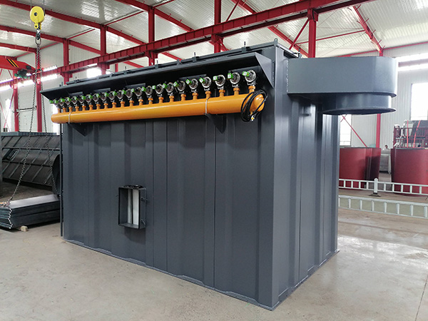
A baghouse dust collector is only as good as its cleaning system, and in a pulse-jet collector that system is the compressed air pulse valve assembly. The valve itself is a modest device—a few kilograms of metal and rubber—but its interaction with the tank, the blowpipe, and the controller determines whether filter bags last eighteen months or eighteen weeks. This article breaks down the system from first principles, explains the key settings, and highlights the sizing and installation decisions that separate a well-performing collector from a chronic pressure problem.
The Core Components of the System
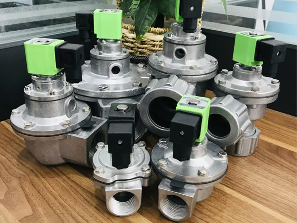
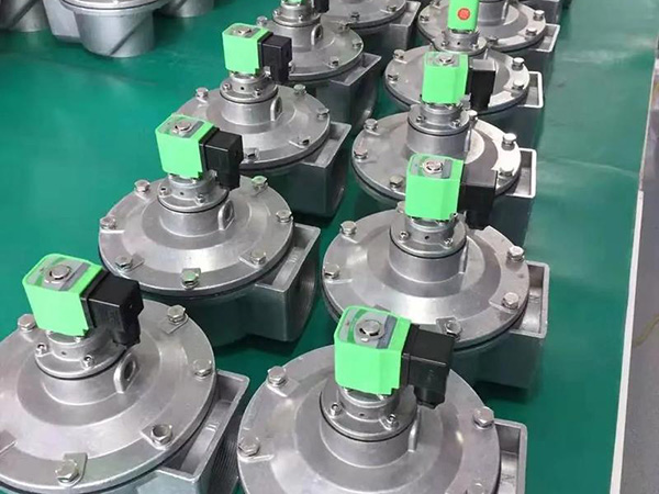
The compressed air pulse valve system has five functional blocks. The compressor provides the air, usually at 7 to 10 bar, and feeds a wet storage tank that smooths demand pulses. A refrigerated or desiccant dryer treats the air to remove moisture, which is critical in humid environments. The clean-air tank holds a reserve volume so that sequential valve firings do not starve each other of pressure. The pulse valve itself meters a precise burst into the blowpipe at intervals defined by the controller. Finally, the blowpipe distributes the air to individual bag locations through precisely drilled nozzles.
Why Tank Sizing Matters More Than People Think
A common mistake in new installations is specifying a receiver tank that is too small. When several pulse valve units fire in rapid sequence—as they do on most controllers—the downstream valves draw heavily from the tank. If the tank volume is insufficient, pressure sags between firings, and the last bags in the sequence receive a weaker pulse than the first. The rule of thumb is a minimum of 10 liters of tank volume per valve in the group, but plants with high cycling rates or long blowpipe runs benefit from going larger. Sizing it right at the design stage costs little; undersizing it creates a chronic performance problem.
Pressure Settings and Their Effect on Cleaning
Most baghouse applications perform well between 5 and 6 bar at the valve inlet. Below 4 bar, cleaning is often insufficient even with a correctly sized tank, and the collector pressure climbs steadily. Above 7 bar, the pulse becomes aggressive enough to flex the fabric more than necessary, accelerating fatigue in the filter media. The sweet spot for most needlefelt and membrane bags sits between 5 and 6 bar. The controller typically offers two adjustable parameters: the pulse width in milliseconds and the interval between pulses in seconds. Wider pulses add energy but waste air; longer intervals let the cake thicken between cleaning cycles.
Air Quality Requirements for Reliable Valve Operation
A compressed air pulse valve is unforgiving of dirty air. Oil, water, and solid debris all degrade the diaphragm and the solenoid. In our experience, the single most common cause of premature valve failure in the field is inadequate air drying. A refrigerated dryer removes bulk moisture but can leave the air saturated in cold weather; a desiccant dryer is the right choice for year-round reliability in ambient conditions below 5°C. Point-of-use filters at each valve—typically 5-micron and 0.01-micron elements in series—catch whatever remains in the line and are cheap insurance against costly unplanned shutdowns.
Blowpipe Design and Nozzle Sizing
The blowpipe must be sized to match the compressed air pulse valve capacity and the number of bags per row. Nozzle diameter and spacing determine how the jet is distributed along the bag length. Nozzles that are too large cause the air to spread and lose velocity; nozzles that are too small create excessive back-pressure that starves adjacent bags. The nozzle sizing calculation should account for the number of bags, the bag length, and the available pressure drop across the blowpipe. A competent supplier provides a blowpipe drawing with nozzle sizes pre-calculated rather than a generic catalog pipe.
Controller Integration and Sequencing
The controller manages the firing sequence so that adjacent rows do not pulse simultaneously. Simultaneous firing on a compressed air pulse valve system starves the tank and wastes air because two valves compete for the same compressed volume. Most controllers support variable timing and on-demand triggering based on differential pressure. On-demand control reduces air consumption significantly—our factory measurements show 15 to 25 percent savings compared to fixed-interval firing—and is the preferred mode for any collector with variable dust loading.
Sizing Example for a Typical Plant Application
Consider a collector with 200 bags, 10 rows of 20 bags each. With a 200-liter receiver tank and 10 valves cycling in groups, the tank-to-valve ratio is 20 liters per valve, which comfortably meets the sizing rule. At 5.5 bar, 100 ms pulse width, and a 30-second interval, the estimated air consumption is roughly 0.8 Nm³ per minute. If the collector runs continuously, this translates to a compressor energy cost that justifies investing in a properly sized dryer and point-of-use filters to protect the valve life.
Frequently Asked Questions
What pressure is required for a compressed air pulse valve system?
Most systems operate reliably between 5 and 6 bar at the valve inlet. Lower pressure reduces cleaning effectiveness; higher pressure increases fabric stress and air waste.
How do I size the receiver tank?
Aim for a minimum of 10 liters per valve in the firing group. Larger tanks reduce pressure fluctuations during sequential firing and improve cleaning uniformity.
Why does my collector pressure drop suddenly after a batch of pulses?
This usually indicates tank pressure sag from undersizing or from too many valves firing simultaneously. Check tank volume and controller sequencing to ensure adjacent rows stagger rather than overlap.
How does on-demand pulsing differ from interval control?
On-demand control triggers pulses based on differential pressure setpoints rather than a fixed clock. It uses significantly less compressed air and extends both valve and bag life.
Conclusion
A well-designed compressed air pulse valve system is the foundation of reliable baghouse performance. Size the tank correctly, maintain air quality, match the blowpipe nozzles to the valve capacity, and prefer on-demand control over fixed-interval firing. These choices are made once at design or overhaul and pay dividends in lower air consumption, fewer valve failures, and longer filter bag life throughout the campaign.
References
Simon, X., et al. (2008). Pulse-jet cleaning of filter bags: effect of operating parameters. Powder Technology, 186(3), 256–264.
Fan, Y., et al. (2015). Effect of pulse parameters on cleaning performance of filter bags. Powder Technology, 271, 92–99.
Lei, H., et al. (2011). Numerical simulation of pulse-jet cleaning in fabric filters. Industrial & Engineering Chemistry Research, 50(12), 7469–7476.
Zheng, Y., et al. (2018). Influence of solenoid valve timing on filter cleaning. Aerosol and Air Quality Research, 18(4), 1021–1030.
 HOT PRODUCT
 CONTACT US